
 中文
How to set the parameters of a blasting vibration meter? The following is the parameter setting method of the TC-4850. Factory devices come with default parameters and basically need no modification.
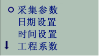 There are two ways to set the instrument parameters: one is via the bundledBVA analysis software (see the software manual); the other is directly via the keys on the instrument panel.
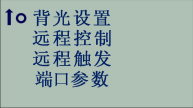 Before testing, the working parameters must be set to ensure the signal is collected effectively and accurately. Parameters include sampling frequency, trigger level, trigger mode, sampling time, sampling delay, etc.Special note: this instrument requires no range setting - the system auto-adapts the range.
Trigger Level
To prevent false triggering caused by noise from environmental interference, a threshold must be set - the trigger level.Note: if the trigger level is set too high, the instrument will not trigger and the signal cannot be recorded; if too low, it will trigger falsely.
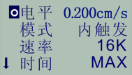 Setting method:Enter parameter settings- Acquisition Parameters - Level screen. Move the circle cursor to the "Level" menu, press "OK" to turn the cursor background black and enter edit mode; use the up/down keys to change the value and the left/right keys to select the digit to edit.Other parameters are set similarly.
The trigger level of this instrument uses physical quantity scales. For example, if the vibration amplitude is7 cm/s, to ensure the signal is collected effectively while avoiding false triggering from surrounding interference, we can set the trigger level to 20% of the amplitude, i.e. 1.40 cm/s.
Recommendation:Before testing, estimate the signal amplitude of this test and set the trigger level to a percentage of the peak amplitude of the measured signalof the peak -20%this avoids interference-induced false triggering while ensuring reliable triggering of the valid signal.
Trigger Mode
Location: parameter settings- Acquisition Parameters - Mode
The instrument has two trigger modes: internal and external. Internal triggering is level triggering - when the signal exceeds the set trigger level, the instrument triggers instantly and starts acquisition; external triggering is via an attached wireless module.
In internal trigger mode, after setting the trigger level the user may leave; when the signal exceeds the level, the instrument starts recording.
Note: this instrument uses three-channel parallel acquisition - when any channel reaches the trigger value, all channels sample simultaneously.
Sampling Rate
Location: parameter settings- Acquisition Parameters - Rate
Sampling Ratefor analog-to-digital (A/D) conversion, the interval between sampled points, in units ofisSPS(samples/per second),Usually set according tothe frequency of the measured signaland selected accordingly.。
Engineering vibrationfrequencies are generally around100Hzapproximately,To make the collectedsignalcomplete while avoiding high-frequency noise,we need toset the samplingfrequencyto a multiple of the signal frequency10~100times(1KHz~10KHz)that is,each vibration periodrequirescollecting10~100sample points to ensure the measured waveform is not distorted.
Before testing,estimate the frequency of the measured signal and set the sampling rate accordingly. An improper sampling ratewill causealiasing or waveform distortion of the collected,signal,introducing measurement errors.。For routine blasting vibration tests, a sampling rate of8KHzor16KHzis recommended.
This instrumenthas5sampling rate options for users to choose from,1K、2K、4K、8K、16K、32K、50Kmeeting various test scenarios.。
Sampling Time
Location: parameter settings- Acquisition Parameters - Time
Sampling TimeThe time from trigger-start to recording completion. This instrument offers:seven sampling time options: 1 s, 2 s, 5 s, 10 s, 20 s, 50 s and MAX, whereMAX represents the maximum sampling time.The sampling length of this instrument is fixed at160K, hence:
Sampling Time= sampling length (160K) / sampling rate
Therefore the maximum sampling time differs at different sampling rates, and the selectable sampling time cannot exceed the maximum,for example:set16KSampling Rate,by the above formula the maximum sampling time is10s,so when setting the sampling time you can choose from1s、2s、5s、10s、MAXthese options.
The selectable sampling times at different sampling rates are shown in the table below:
Sampling Rate | Selectable sampling time |
1K | 1s、2s、5s、10s、20s、50s、MAX(160s) |
2K | 1s、2s、5s、10s、20s、50s、MAX(80s) |
4K | 1s、2s、5s、10s、20s、MAX(40s) |
8K | 1s、2s、5s、10s、20s、MAX(20s) |
16K | 1s、2s、5s、10s、MAX(10s) |
32K | 1s、2s、5s、MAX(5s) |
50K | 1s、2s、MAX(3.2s) |
Sampling Delay
Location: parameter settings- Acquisition Parameters - Delay
 Sampling DelayCan be set as positive or negative delay.To avoid losing the signal header before the trigger, a certain space must be reserved in the signal buffer to store it,i.e. pre-saving data before the trigger point - this requires setting a negative delay. Positive delay is the opposite.
The instrument sampling delay can be set to:-2000ms—2000ms。
Note: the sampling delay must be smaller than the sampling time, otherwise acquisition fails. (E.g. if the sampling time is set to1s, the sampling delay must be set between-1000ms~1000msand must not equal-1000msor1000ms, and so on.)
Date Setting
Location: parameter settings- Date Setting
Date setting includes year, month and day.,The first two digits of the year are fixed as20,users can only set the last two digits.
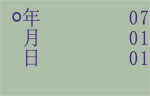 1、Year:of the peak -The setting range is:00—99;
2、The month range is:01—12;
3、The day range is:01—31。
Time Setting
Location: parameter settings- Time Setting
Time setting includes hour, minute and second.
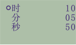 1, using a24-hour system; the range is:00—23;
2Minutes range:00—59;
3Seconds range:00—59。
Engineering Coefficients
Location: parameter settings- Engineering Coefficients
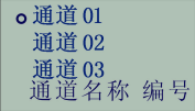 Sensors connected to different channels need their own engineering coefficients: calibrationCH1, calibration CH2, calibration CH3.
Channel name:can be represented by a numberCH(1,2,3)or directionCH(X,Y,Z).
Co-efficient:i.e. the sensitivity coefficient. Each sensor has its corresponding calibration parameter at the factory; its accuracy directly affects test precision.
Offset:i.e. bias or zero offset, inV. Like the sensitivity coefficient, this value is factory-given.
Unit:divided into velocity (m/s), acceleration (g), arbitrary international unit (EU), voltage (V), temperature (℃), pressure (Mpa). When connecting different sensors, remember to change the engineering unit.
Backlight Time
Location: parameter settings- Backlight Time
The instrument backlight is selectable from0s to60s;0s turns the backlight off. It is recommended to set the backlight within5s to save battery.
Remote Control
Location: parameter settings- Remote Control
This function is active when a wireless telemetry module is attached.
Device address: instrument address001-255 settable;
Parameter access: allow/deny remote setting or modification of parameters;
Start acquisition: allow/deny remotely controlled acquisition;
Data access: allow/deny remote data access.
Remote Trigger
Location:Parameter Settings- Remote Trigger
Alarm: allow/denyGPRSwireless alarm;
Input: allow/deny the wireless module receiving signals;
Output: allow/deny the wireless module sending signals;
Test: when the wireless module input and output are allowed, the communication between two wireless modules can be tested.
Threshold: set the alarm threshold; when measured data exceeds it, the instrument sends an SMS alarm to the designated phone.
Port Parameters
Location:Parameter Settings- Port Parameters
Rate: set the wireless module transmission rate;
Parity: odd/even/none;
USB: autoUSB, active when the interface is plugged in; enableUSBto keep it always active.USB
Alarm Numbers
Location:Parameter Settings——Alarm Numbers
Active when an SMS alarm module is attached; enter phone numbers in the format:86xxxxxxxxxxx
Peripheral Power
Location:Parameter Settings——Peripheral Power
Enable when connecting sensors requiring extra power, such as acceleration, low-frequency and shock-wave sensors.
Data Acquisition
Location: data acquisition
After parameters are set, the instrument can start acquisition. Select“Data Acquisition" to enter the "waiting for trigger" screen; when a signal exceeds the set trigger value it will be recorded (acquiring), as shown below:
Current count:the number of this acquisition;
Total count:the total number of acquisitions of the instrument, i.e. all stored data.
After acquisition, press any key to stop and return to the main screen.Note: do not plug/unplug sensors during data acquisition.
Data Analysis
Location: data processing- Data Analysis
throughThe "data analysis" function reads signal characteristic values and previews waveforms:
Peak:the maximum amplitude of this channel;
Main frequency:the frequency corresponding to the maximum amplitude;
Channel:the three channels can be switched freely.
Note:USBUsing the data analysis function while connected to a host computer may cause instrument faults.
Status Detection
Displays the instrument power, time, serial number and system self-test.
Power Status
Location: system status- Power Status
The instrument is powered by a lithium battery; via the “Power Status" function you can check the battery level. When the battery voltage is within3.5V the screen dims as a charge reminder; when the voltage is below3.2V, the instrument shuts down automatically. Please charge promptly when battery voltage is low - at least 4 hours per charge; a full charge powers the instrument for 60 hours.
Remarks: At full voltage,the instrument should not be stored longer than5 months, otherwise the battery will be over-discharged.
System Detection
Location: system status- System Self-Test
The system self-test covers read-only memory, flash memory, programmable memory andUSB status. If an error occurs in the self-test the instrument cannot be used - please contact us promptly.
Other
Current time:Displays the current time.
Serial number:Displays the factory serial number of the instrument.
Software version:Displays the underlying software version.
Data Management
File Deletion
Location: data processing- File Deletion
After entering the file deletion menu, the screen shows all file names, the space occupied by existing files and the remaining memory. To delete a filethe specific operation is as follows:
The system defaults to deleting the first file. Use the and keys to select the file to delete, press the“OK" key to delete the data file, press the“Cancel”key to return.
Disk Formatting
Location: data processing- Disk Formatting
Disk formatting:Erases all data in the instrument. The specific operation is as follows:
After entering the disk formatting menu, the system prompts whether you really want to perform the operation. Press OK to start formatting, or Cancel to abort.
