
 中文
In drill-and-blast tunnel construction, the seismic waves generated by blasting spread into the surrounding rock and can easily disturb the formed surrounding rock, primary support and secondary lining behind the tunnel face. If vibration exceeds limits, at best shotcrete cracks and spalls; at worst the surrounding rock loosens, structural cracks form in the secondary lining, or even collapse accidents are induced.
Therefore, blasting vibration monitoring of the tunnel's own bore is the core control means for quality, structural safety risk avoidance and blasting parameter optimization. This article, based onGB 6722-2014 "Safety Regulations for Blasting"andT/CSEB 0008-2019 "Technical Code for Blasting Vibration Monitoring"the two authoritative standards, comprehensively explains in-tunnel monitoring point layout, sensor installation, safety control standards and terminology, providing a standardized operation basis for site construction.
I. Monitoring Standards and Monitoring Objects
1. Standards followed
(1) National mandatory standard: GB 6722-2014 "Safety Regulations for Blasting" - defines the safety allowable vibration velocity of protected objects and the basic mandatory monitoring requirements;
(2) Industry-specific code: T/CSEB 0008-2019 "Technical Code for Blasting Vibration Monitoring" - regulates field point layout, equipment installation, section arrangement and other operational details.
2. Core monitoring objects
The supported bore structure behind the tunnel face blasting, including: original surrounding rock, primary support structure and secondary lining. Unlike surface monitoring and adjacent structure monitoring, this monitoring focuses onthe safety of the tunnel structure itself。
II. Monitoring Section Layout Specifications (with original code text)
1. Requirements for the nearest monitoring section
In routine tunnel blasting monitoring, the distance of the first monitoring section is the most error-prone item on site. Per the official provisions of T/CSEB 0008-2019:
Original code text (6.1.3):When the measured object is the tunnel itself, the nearest monitoring point should be on the bore wall 2 bore-diameters from the blast zone, at 1/3 of the bore height from the floor.
Simply put: for routine safety monitoring, the monitoring section nearest to the blast zone (face excavation edge) shall be set at2 tunnel bore-diameters behind the face- also the mandatory layout starting point commonly used in the industry.
To adapt to complex site conditions, a practical fallback rule is added: verified by extensive field construction, to avoid shock wave damage to monitoring equipment and ensure data validity, regardless of bore diameter, the nearest monitoring section distancemust be no less than 10 m。
2. Multi-section arrangement
Routine safety control (normalized construction)
Only 2 monitoring sections are needed for construction: the near-blast section (2 bore diameters) monitors peak blasting vibration velocity in real time, directly controlling the safety of each blast; the far reference section (10-15 bore diameters) observes the vibration attenuation law and checks for hidden cumulative damage to the lining. If the surrounding rock is fractured, the burial is shallow, or geological conditions change abruptly, densify to 3-4 monitoring sections.
Test optimization stage (blasting parameter tuning)
To fit the Sadovsky attenuation formula V=K(Q/R)^alpha and optimize charge quantity, millisecond staging and other blasting parameters, follow the"dense near, sparse far"principle, arranging no fewer than 5 gradient sections covering 2, 3, 5, 8 and 12 bore diameters, with no fewer than 5 valid data sets per acquisition.
III. Single-Section Point Layout and Equipment Installation
1. Point layout scheme
Per the two codes, a single monitoring section requires3 triaxial vibration monitoring points, forming a complete monitoring system:
Left/right arch haunches: points at 1/3 of the bore height from the floor, preferably on the blast-facing side, monitoring horizontal vibration;
Crown center: dedicated to vertical vibration monitoring; this position is a high-frequency risk area for lining tension cracking and spalling.
2. Sensor installation specifications
All points must be equipped with triaxial vibration sensors, acquiring three-dimensional data synchronously: X (tunnel axial), Y (circumferential horizontal tangential), Z (vertical); sampling rate >= 1,000 Hz.
Installation differs by support type: in primary support sections, fix sensors with expansion bolts; in secondary lining sections, clean the surface laitance first and fix with gypsum anchoring or chemical anchors, ensuring the base fits tightly to the structural face with no hollowing or loosening to guarantee data accuracy. Route signal cables along wall bases with protective casings to prevent construction damage.
IV. Blasting Vibration Safety Allowable Standards and Terminology
Based on the safety allowable particle vibration velocity standards of GB 6722-2014 and the different support structures and surrounding rock grades of tunnels, three control categories are classified, with professional terms explained for quick on-site judgment:
1. Intact reinforced-concrete secondary lining | Allowable velocity: 7-15 cm/s
The secondary lining is the permanent load-bearing structure of the tunnel and the last safety line. With a complete rebar cage, C25/C30 impermeable reinforced concrete, main bars, stirrups and distribution bars, it has high overall stiffness and optimal vibration/tension resistance - hence the highest safety threshold. Only when the lining has through cracks, rear voids or corroded/debonded rebar should the control threshold be lowered.
2. Plain-concrete primary support, fractured surrounding rock | Allowable velocity: 3-7 cm/s
The primary support is a temporary structure built immediately after excavation, typically shotcrete + rock bolts + steel mesh; no load-bearing main rebar frame, relying only on a thin concrete layer wrapping the rock. Fractured rock has developed fissures and poor integrity; combined with the brittleness and crack-proneness of plain shotcrete, overall vibration resistance is weak - exceeding limits easily causes shotcrete spalling and bolt loosening.
3. Extremely fractured Grade IV/V surrounding rock | Strict control: 3-5 cm/s
The larger the rock grade number, the poorer the stability. Grade IV rock is soft and fractured - excavation easily spalls blocks and causes small collapses; Grade V rock is mostly fully weathered strata, fault fracture zones and loose soft rock with almost no self-stability. Such sections must use strong support like steel arches and advanced small ducts; the loose rock is vulnerable to vibration damage and is the highest-risk zone of tunnel blasting - the lowest velocity standard must be strictly enforced on site.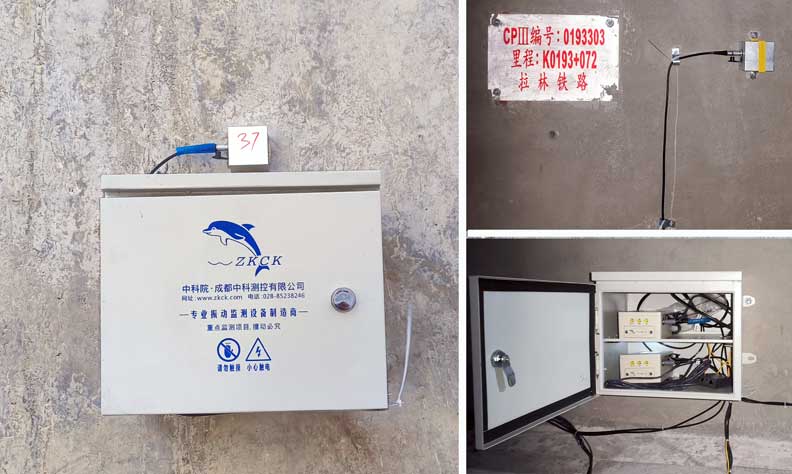
V. Field Operation Summary and Suggestions
Standardized point layout: the first section of routine monitoring is fixed at 2 bore diameters behind the face (and >= 10 m), with a standard 3 groups of triaxial points per section: crown + double haunches;
Graded threshold control: secondary lining at 7-15 cm/s, ordinary primary support/fractured rock at 3-7 cm/s, Grade IV/V extremely poor rock strictly at 3-5 cm/s;
Dynamic optimization: when a single blast velocity approaches or exceeds the threshold, immediately reduce the maximum charge per delay, increase the number of delay stages, and optimize cut-hole and perimeter-hole blasting parameters to eliminate safety hazards.
Blasting vibration monitoring is not a formality but the core means of dynamically balancing construction efficiency and structural safety. Only by strictly laying points and controlling velocity per national and industry standards can blasting construction risks be avoided at the root, ensuring high-quality, high-efficiency tunnel engineering.
